I don’t have a Datasheet. I only have the following informations: CANopen,Baudrate 250kBit. And what I wrote in the previous message.
What kind of slave/manufacturer is this when no datasheet and no EDS is available ?
Any manufacturer should at least provide a datasheet (and in my opinion also an EDS file)
I am working on a school project for a company. The company uses custom-made sensors. We were told that this information is enough. Datasheets and EDS files are not needed and will not be shared as they are security-critical.
Well I am afraid we cannot help any longer - or at least I am out of ideas.
@christoph.hilchenbac tests showed it is working for him without any issue and my tests showed it works when the slave receives a NMT command to reboot
I cannot tell why your sensor/program does not work. I still think that this sensor does not send a bootup message
I don’t think the community can help much here without further information.
If you can’t provide at least a CAN trace we are never sure the sensor is working.
What information should I try to gather so that you can assist me further? As I mentioned, I can’t get the complete data sheets.
A CAN trace as already mentioned showing the bootup message of the device
As a sidenote I do not understand the “security” issue regarding EDS file and documentation. Why would this 2 files result in a security issue ?
Furthermore CAN is not secure at all and anyone who has access (physical wise) can simply fake messages causing severe issues on this CAN bus so I rather find it strange to speak about security in combination with CAN
Yes, they are properly set and used.
Thats odd… I did another test and again it is working fine. Although I have to admit I do not use a C70 as I do not have one at the moment
-
how did you set the baudrate ? Are there some switches for this ?
Or is the baudrate automatically detected (which does not work if there is no initial CAN communication). -
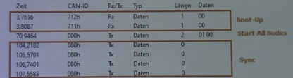
is the screenshot from the current network or was the recording made in a second network for testing ? I wonder who then sends the NMT and the SYNC if there is only one network.
I set Baudrate 250 kBit. The screenshot is from another network.
I think the question was more related to the slave. How do you set this baudrate on the slave ? For example our slaves have (most of the time) Autobaudrate. This means the slave needs “someone” on the bus which sends telegrams as otherwise it cannot send a bootup as it simply does not know the baudrate
I set the Baudrate from my IF 6 CAN port on 250 kBit because i know that this is the Baudrate of the sensor.
Gesendet von Outlook für iOS
The screenshot of the trace is from a different network ? Who did this trace and why don’t you trace your network where this is not working ?
The screenshot is from a different network. I just have to check if the sensor is still working. I don‘t know who did the trace . I don‘t know what you mean by trace your network? I only hava my SPS and the Sensor.
Honestly this is a bit weird. Someone provided this trace to you and you do not know from whom this is ?
With “your network” I am talking about the current setup you have.
Hi.
As Viktor mentioned earlier, this is a school project, and the trace may come from the company that hasn’t yet set up a proper datasheet for their sensor—possibly due to security concerns ![]() .
.
To make some progress, I suggest starting at the physical layer.
Viktor already confirmed that the wiring and resistors are okay. A simple way to check this:
• Power off all devices and measure the resistance between CAN-H and CAN-L. It should be around 60 Ohms.
• To check CAN-H and CAN-L voltages, use a voltmeter while the bus is powered.
Viktor, since this is a school project, you might have access to an oscilloscope, which would be very useful for checking if any signals are being transmitted. I won’t go into too much detail here, as there are plenty of resources online about debugging a CAN bus with a scope.
If you see activity on the bus, it makes sense to move up to the next communication layer. Maybe your oscilloscope supports CAN decoding or you have access to a serial decoder or an Arduino with a basic CAN shield (e.g., MCP2515)?
If you can decode messages or at least share a screenshot of the oscilloscope output, the community’s can help analyze the data and provide B&R-specific insights.
But in my understanding - in this case your task would already be done as this could prove the sensor is at least working a little bit.
Hope this sheds some light on the issue.
Translation:
I am supposed to design a testing tool to which CANopen sensors can be connected and which checks whether communication can be established. I would have done this with a B&R PowerPanel and the FUB CANopenRecvBootup.
The sensors that were lent to me are working. I just can’t establish communication between the sensor and the PowerPanel.
Übersetzung:
I don’t have access to a microcontroller with a CAN interface, nor to an oscilloscope with CAN support.
Okay.
Then you can still double-check the electrical basics of your bus line (resistance in off-state / voltage in on-state) and provide us with a screenshot of your interface configuration.
Maybe there is still something off.