Hi All,
I’m programming a machine and need some coding help.
I want to calculate the circumference of a cilinder.
This cilinder has a gearwheel on its ends which connects to the motor that rotates, and one of the gears has a marking which is detected by a homing sensor. After homing (so position set to 0) we need to start calculating the circumference. After it has once more seen the sensor, it knows the value and stops.
We are doing this with an acopos drive + motor, and the axis is set to linear periodic because we want to know millimeters/second.
The value range for axis positions (period settings) is set to 3600000 (stolen from the previous machine, but absolutely unsure as to which units they used, not documented that well).
I don’t know if these settings are right and if they are needed.
I’m not a genius at calculations so any help in the right direction would help.
My thought proces is:
- Homing to 0
- Start rotation
- Homing sensor is seen again, position := endposition - startposition
- after that I probably need details like gear sizes, and further develop a calculation
Any help welcome!
Hello,
I read the text twice but i am still not sure how the mechanic looks like and how the gears are connected.
Is it possible to share a CAD-Picture or provide a sketch/block diagram?
Please make sure you don’t violate an NDA, only share puplic data.
The messurement is not a periodic process so it currently does not make sense to have a periodic axis.
What does the machine do with cylinder after the mesurement?
Greetings
Michael
Dear Michael,
Thank you for your answer. You are right, my description is quite vague because of the diplomacy around the project, as is with any project. I asked my colleague and can share some details.
What we are programming is a rotary screen printer. The cilinder in question is the “screen” (or cartridge) through which ink is pressed onto a substrate.
The screen is first laid into the machine into a type of drawer. then it is picked up by pneumatic suspension. it is coupled with another gear wheel that is located on the counter roller.
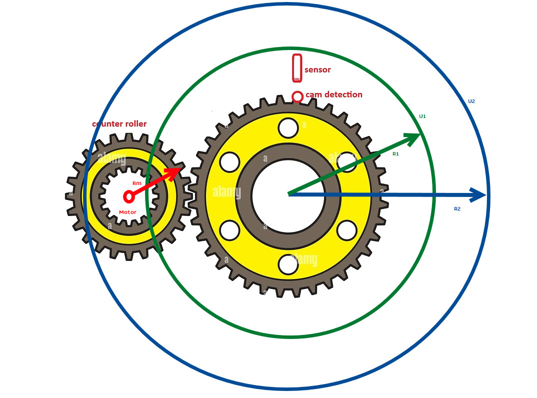
We will first home the screen so that the cam marking is seen by the sensor. after that we want to calculate the circumference. I tried to draw it out a little bit, hopefully it is more clear now.
After calculation we will have the circumference.
We will then rotate slowly and wait for a master encoder on the substrate motor to run fast so we as the slave can start syncing with the master.
Then we use a register mark sensor to correct the position with respect to the substrate paper. We want to use the B&R block RegMarkDetection for this.
How it is implemented we will also need help with, but this has more priority first.
Thanks in advance.
Hello,
my thoughts and understanding:
The combination as i have realised is
Acopos - Motor - Gear - Cyclinder
The resolution 3600000 seem a 1:10 or 10:1 Gear transmission
So 1 Rotation probably represent 360 Degree.
The sensor could be a reference signal. When referencing mode is activate and the cyclinder rotates it will find the zero position depending to the referencing mode. After referencing is finshed you can calculate.
try to find out the amount of increments when the cyclinder does one rotation (probably 360 multiplied with 100 or 1000 or more).
when you got it, you can use circumference calculation (d * Pi) * akt Degree / 360
Take care about units
Its a guess not reality.
Hello,
I added the different Cylinder sizes to the picture, i hope i am correct.
I am am still thinking of what part of the mechanik is fix (we can use as Constant Values in Calculation and Process) and which parts are varying.
Is the Big Gear changing its size with the Zylinder, so what we want to messure is the circumference of the BigGear?
The small Gear is fix and we know Radius (Rm) and can Calculate Circumference (Um) of the small Wheel.
Greetings
Michael