Hi,
For this example, B&R Online Help , to start sending the commands, do we need to set fMCmd = 1?
Will statusMCmd be set to zero when the command has been sent?
Thanks and Regards,
Kenneth
Hi,
For this example, B&R Online Help , to start sending the commands, do we need to set fMCmd = 1?
Will statusMCmd be set to zero when the command has been sent?
Thanks and Regards,
Kenneth
Hi Kenneth,
on the page you linked, “fCmd” does not appear anywhere, so what exactly makes you think a variable of that name exists or does something?
Thanks for pointing out. I have updated the link above. I was looking at the code for the master.
It should be fMCmd.
Hi,
for me, the sample code looks like that
If the commands are sent successfully and response data was received (means: MBMCmd returns status 0 → “green” part in the screenshot below), the sample stays in “send command mode” (by fMCmd = 1 statement). Since it’s a asynchronous function block, the sample also keeps calling MBMCmd if function block status returns BUSY (MBMCmd returns 65535, “yellow” part).
If the return status is neither 0 nor 65535, MBMCmd returned an error and fMCmd is set to 0 (“red” part).
Best regards!
Thanks Alexander.
I am currently encountering an error in the initialization portion of the code:
MOpen.enable = 1;
MOpen.pDevice = (UDINT) &device[0];
MOpen.pMode = (UDINT) &mode[0];
MOpen.pConfig = (UDINT) &config[0];
MOpen.timeout = timeout;
MOpen.ascii = ascii;
MBMOpen(&MOpen);
statusMOpen = MOpen.status;
MBMOpen returns a status 20241. Or sometimes it does not return. Does anyone know what could be the issue?
It seems I have not defined the mb_cmd data object. I will try to include it in my project. How does it relate to the CmdTable object?
Thanks and Regards,
Kenneth
After I added the mb_cmd data object, I get the same behavior. Do we need to call MBMOpen for modbus to work? Below is the code I am using the initialize the modbus, but I cannot get the correct status (I get 20241) for MBMOpen:
void ModBusInit (void)
{
/* modbus VAR /
pEventMB4 = &EventMB4;
pDataMB4 = &DataMB4[0];
EventMB0 = 1;
EventMB1 = 1;
EventMB3 = 1;
EventMB4 = 1;
DataMB4[3] = 8000;
DataMB4[4] = 30000;
DataMB4[5] = 0;
i = 0;
/ init for OPEN /
ascii = 0; / 0 = RTU / 1 = ASCII /
strcpy(&device[0], “IF1”);
strcpy(&mode[0], “PHY=RS485/BD=57600/PA=N/DB=8/SB=1”);
strcpy(&config[0], “mb_cmd”);
timeout = 500;
/ data /
data[0] = 0x04;
data[1] = 0x05;
data[2] = 0x45;
data[3] = 0xFF;
data[4] = 0x00;
data[5] = 0xFE;
/ modbus - Slave OPEN */
MOpen.enable = 1;
MOpen.pDevice = (UDINT) &device[0];
MOpen.pMode = (UDINT) &mode[0];
MOpen.pConfig = (UDINT) &config[0];
MOpen.timeout = timeout;
MOpen.ascii = 0;
MBMOpen(&MOpen);
statusMOpen     = MOpen.status;

if (!statusMOpen) ident    = MOpen.ident;
fMaster         = 0;
fMCmd           = 0;
fMClose         = 0;
fMOpen = 0;
}
Hi,
I think it’s neccessary first to explain the content of the whole C demo code a bit more.
This demo code shows all different possibilites how the modbus master can be used:
So, in a nutshell, the demo code includes all variants that are possible.
And why the’re 2 different ways for defining the communication exchange? Because it depends on the use-case you have to realize:
Independent of you want to use MBMMaster() or MBMCmd(), you always need to initialize the modbus driver with MBMOpen().
And, as I know (please note that I haven’t used it for a long time!), since MBMOpen() needs to be linked to the config data module, a valid data module has to be defined & transferred, even if you only want to use MBMCmd() later on
→ if you don’t want to use the definitions out of the data module, since MBMOpen() needs the data module nevertheless, for example just create one valid line as a dummy and connect the data module name with the suitable MBMOpen() input… as long as you don’t call MBMaster, the data module definitions aren’t processed.
Hope that makes it a bit more clear.
Best regards!
About your question:
It’s hard to say because of the formatting of the copied code here in the forum, but it looks like that the value setup of “device”, “mode”, and “config” are commented out.
That means you’re calling MBMOpen with .pDevice = 0, .pMode = 0, ,Config = 0 → but the’re valid values needed for the interface definiton and the data module name to get the master initialized.
Thanks for the information, it is helpful. I will add a valid data object.
Would adding the below contents to a mb_cmd.dat file under DataObject be sufficient to define the mb_cmd data object?
" ", 03, $02, “DataMB4[0]”, 0000, 0003
" ", 06, $02, “DataMB4[3]”, 0003, 0001
" ", 16, $02, “DataMB4[4]”, 0004, 0002
" ", 02, $02, “DataMB1[0]”, 0000, 0005
" ", 01, $02, “DataMB0[0]”, 0000, 0003
" ", 05, $02, “DataMB0[3]”, 0003, 0001
" ", 15, $02, “DataMB0[4]”, 0004, 0002
I tried to create the mb_cmd data object, but I still get the issue that Mbmopen is stuck and does not seem to return with an error code.
Sounds strange, especially the “stuck”.
Can you tell me please a bit more in detail what hardware and software you’re using?
Best regards!
Hi,
The CPU is X20BB52.
I am using X20CS1030 with IF1. It is on B&R X2X link.
The Automation Studio version I am using is 4.7.2.98.
Where can we determine the Automation Runtime version? The Runtime Utility center version I have is PVI 4.7.
Below is an extract of the code (C++) which I have an issue with. It gets stuck in the MBMOpen function.
Thanks and Regards,
Kenneth
void ModBusInit (void)
{

	pEventMB4               = &EventMB4;
	pDataMB4                = &DataMB4[0];
	EventMB0                = 1;
	EventMB1                = 1;
	EventMB3                = 1;
	EventMB4                = 1;
	DataMB4[3]              = 8000;
	DataMB4[4]              = 30000;
	DataMB4[5]              = 0;
	i                       = 0;

	ascii                   = 0;
	strcpy(&device[0],  "IF1");
	//if (!ascii)    strcpy(&mode[0], "PHY=RS232/BD=9600/PA=E/DB=8");
	//else           strcpy(&mode[0], "PHY=RS232/BD=9600/PA=E/DB=7");
	//if (!ascii)    strcpy(&mode[0], "PHY=RS485/BD=57600/PA=N/DB=8/SB=1");
	//else           strcpy(&mode[0], "PHY=RS485/BD=57600/PA=N/DB=7/SB=1");
	strcpy(&mode[0], "PHY=RS485/BD=57600/PA=N/DB=8/SB=1");
	LogMsg("before strcpy", LOG_SEVERITY_INFO);
	strcpy(&config[0],  "mb_cmd");
	timeout         = 500;

	data[0]         = 0x04;
	data[1]         = 0x05;
	data[2]         = 0x45;
	data[3]         = 0xFF;
	data[4]         = 0x00;
	data[5]         = 0xFE;

	MOpen.enable    = 1;
	MOpen.pDevice   = (UDINT) &device[0];
	MOpen.pMode     = (UDINT) &mode[0];
	MOpen.pConfig   = (UDINT) &config[0];
	MOpen.timeout   = timeout;
	MOpen.ascii     = 0;


	MBMOpen(&MOpen);
	statusMOpen     = MOpen.status;
	char str[40];

	sprintf(str, "init Mopen status: %d", statusMOpen);

	if (!statusMOpen) ident    = MOpen.ident;
	fMaster         = 0;
	fMCmd           = 0;
	fMClose         = 0;
	fMOpen = 0;
	fRead 			= 0;
}
Hi,
since I haven’t AS4.7 available anymore, I can’t do any testing: so the following information and screenshots refer to AS4.12 → I cant swear that everything looks similar, sorry.
Also please note, that all the screenshots of hardware and versions are examples only, and will differ from what you have in your project.
Also, I can’t say if the two topics below are the cause for the behavior or if there’s even more behind in the code a.s.o., but I’m definitely sure about that you have to check and change at least those topics.
If using a X20CS… communication module, the device string cannot be “IF1” only - the device string has to be the complete interface path. As a example: if a module is plugged onto X2X bus, the interface path is at least something like < X2X Interface >.< X2X Slot >.< Module interface name >
For example: let’s assume the X2X interface is IF6, the CS module is the third on the bus, and the interface on the CS module is IF1, then the device string is “IF6.ST3.IF1” (see sample screenshot below).
If using a X20CS… module together with serial frame driver (the MBxxxxx() functions are using that driver called “DvFrame”), the module has to be configured to the function model “stream” or “cyclic stream” (has do be done in Automation Studio, configuration of the module).
Sample screenshot of AS hardware configuration to see how the interface string is built (as described above), and to see the setting of the function model in the CS modules configuration:
Two more hints:
1.) the X20BB52 is not the PLC, it’s only a backplane module. The PLC is the “bigger” module plugged into this BB52 … as BB52 is a module for X20Compact-S system, the PLC is something starting with X20CP0xxx, for example X20CP0482, X20CP0411, or similar
2.) the Automation Runtime version (operating system of the PLC) used in your project can be checked (and set/changed) in Automation Studio in the menu “Project → change runtime versions”:
When you’re online to a PLC, the AR version installed on the device (and also the device type itself) is shown in the lower right corner of Automation Studio, at the left of the connected PLC’s operating status:
![]()
Best regards!
Thanks. I will look into the above updates. The Automation Runtime version I am using is C4.72. The CPU model is X20CP0482.
The issue of the function not returning was due to the init function not completing due to a short cycle time allowed for the program. The issue is resolved after I shifted the modbus initialization to a program with a higher allowable cycle time and which performed less operations.
I am now getting a consistent error code 20245, which indicates that a local PV is not defined correctly. The PV was defined as “_GLOBAL” in the example code. I removed the “_GLOBAL” as it could not be compiled in my C++ program.
Is there a way of defining global variables in C++ to be shared by the Data Object?
Thanks and Regards,
Kenneth
Hi there,
if something is there in an example and doesn’t compile, the solution is not to delete it ![]()
That should bring you a little further
Hi,
Thanks for your help. I ported the modbus example code (with _LOCAL and _GLOBAL) to a C test program. It compiles and runs. However, I am still getting the return value of 20245 for MbmOpen. It looks like the issue is not due to the _LOCAL or _GLOBAL macros. I have tried to remove the variable names from the mb_cmd.dat file, but still get the same error code. What would be a valid data object entry in the dat file, assuming we are not using it for sending messages?
On a side note, is there a way to convert integer to string in a B&R C program? I could not use the sprintf command in Automation Studio for a C program. (C++ is ok)
Thanks and Regards,
Kenneth
Hi,
getting status 20245 means, that a process variable, that is used inside the data module, does not exist in the PLC.
You have to mention, that if you declare a process variable (by _LOCAL or _GLOBAL or inside *.var file), but don’t use it anywhere in the code, then for performance reasons this variable is not installed into the PLC (because it’s nowhere referenced).
So you have to:
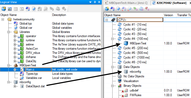
For example let’s assume, your task where MBMopen() is called has the name “MBOpenTest”. Inside “MBOpenTest”, there’s a _LOCAL process variable called “myMbDummyVar” declared.
To use this variable for the data module, you have to
I don’t have suitable hardware to really run some code, but it should look somehow like this:
Best regards!
You can use the “AsBrStr” library, function block “brsitoa()”:
Best regards!