I have B&R x20CP1685 PLC with DC1176 high speed counter.
I am trying to count values using quadrature encoder. Yet i am getting strange values from counter. How can i correct the results. I am adding the configuration in the pictures. Thanks in advance.
The model of the quadrature encoder is Efector 400 RO6352RO-1000-L24.
Resolution: 1000 pulses per revolution
Output: Push-pull (HTL)
I have two signals coming from the encoder, which are connected to the I/O card before for reading values. I disconnected IO card and connected signals A and B to the upper-left buses of the DC1176 converter.
I can see that the signals are toggling between True and False, but the encoder values are not reasonable. They appear as integer values, and sometimes they increase like 1 → 7 → 40, then suddenly go negative. Other times, they go 1 → 3 → 9 → 100, and then again drop to negative values.
I haven’t been able to come up with a reasonable explanation for this behavior
From my understanding, HTL is going to pass the input voltage as the output voltage of the encoder. From reading the encoder’s datasheet, the input voltage is 10-30V. Additionally, if you are triggering standard digital input cards with the signal from the encoder, then the voltage is too high for the ABR encoder inputs of the DC1176.
The DC1176 encoder inputs are 5V symmetrical, so the module is expecting a 5V difference between the A signal and A\ signal to indicate a high value. This is different than what would trigger a digital input, a 24V asymmetrical signal.
If you are only connecting the encoder to the A and B channels (leaving the A\ and B\ channels disconnected), then the module is trying to measure the voltage between the encoder signal and a floating lead. This could also lead to the odd behavior you are seeing.
If you want to use the 24V asymmetrical encoder (single wire A channel, single wire B channel, common gnd), then you need the X20DC1376 module instead.
I put together the following write-up on incremental encoder signal types.
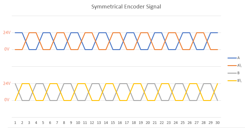
Symmetrical vs Asymmetrical Encoder Signals
Symmetrical encoder signals evaluate the voltage difference between Signal and Signal\. If Signal is greater than Signal\, that is interpreted as a 1. If Signal\ is greater than Signal, that is interpreted as a 0.
Asymmetrical encoder signals evaluate the absolute voltage of the Signal. If Signal is greater than the static 0 → 1 triggering threshold (15V), that is interpreted as a 1. If Signal is less than the static 1 → 0 triggering threshold (5V), that is interpreted as a 0. Between 5 and 15V, the signal is undefined because it depends on the previous triggered state.
(24V version used in diagrams, which does not represent all encoders. Typically, 24V encoders are asymmetrical, 5V are symmetrical, but there are exceptions.)
Thanks for great answer.
It seems it is the problem. Can i use
DMI Converter 1110494-01 - Leine Linde to convert HTL signal to RS422 signal to use DC1176 counter?
Can you please attach the datasheet/website link for the converter here? It takes a while to try to reverse look-up the product specifications by their model numbers, and you will receive better answers if they are easier to research.
It looks like the DMI Converter 1110494-01 - Leine Linde would work to convert the incremental encoder signals to be compatible with the DC1176.
There isn’t a voltage per line over time diagram, so I’d be leaning on the “RS422 Output Level” to mean low voltage differential, and not just low voltage output.