I was going through the Labeler process solution in the help contents using cam automat. Couldn’t find the Axis feature details for this example, the programming and diagnostics were helpful in understanding.
Same for other examples, flying saw and cross cutter. Any idea where I can get the Axis feature parameters used for these examples.
Hello,
The 3 examples for the Cam-Automat can be found in the Toolbox as selectable Packages.
If you add them from the Toolbox to your Configuration view you have the wohle Parameters visible.
Greetings
Michael
Thanks for the help Michael, would be great if a link be provided in the help page directing to look for the package in the tool box.
Hello,
Thanks for the Feedback and good to read that you could find the elements.
When i wrote the last message did not had a AS-Help at hand, so i reviewed it now, with your Feedback in mind. You are right it could be made more obvious were to find these objects.
I may add that the root “Configuration” is the section in AS-Help which only descripes the configuration objects found in the Toolbox. That is what the creators of the help had in mind, i think.
If there are no questions left you might mark a post of this thread as solution, so others can see that this post is solved.
Greetings
Michael
Hi Michael,
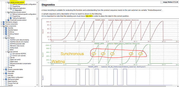
I was able to run the labeler. Just wondering what parameters make the synchronous(cam in) to happen between 500mm and 525mm on the Labeler position axis every period.
Hello,
i am not sure if i got the question right but i will try to take it… and just explain a bit more. I hope i am be lucky to get the answer in it.
lets have a look at the CAM-Automat used for the Labeler. I used the Picture from Powerpoint Atattched to AS-Help. I added the Event-Types so you can see which State-Change occures by which event.
labelerppt.pptx (3.4 MB)
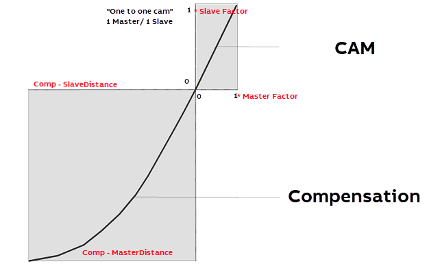
Description of a CAM-State, consisting of the Compensation and the CAM phase.
This Parameters descripe the size of the elements.
The compensation is a automaticaly calculated polynom which is used to alternate the gradient of the cam. The CAM section can be used to have a own curve form definde by a cam or like in this case you can use a predefined cam. The “one to one cam” is a curve which starts with 0/0 and Ends at 1/1. This curve can be scaled to every m/n coupling by the Scaling Factors.
If you start the CAM Automat you are starting in the Start-State 0. Due to the Transition “Event[0]” Type State-End/Immediatly you will find yourself changing to State 1 at the end of State 0. The End of State 0 is defined by the StartPosition Settings. In this case we Start at every Period of the Master going through “0”-Position. If you have not a periodic axis the CAM-Automat can only create this transition at the single “0”-Position as there is not Invtervall.
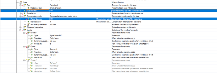
State 1 has a lenght given by Master factor and Master distance.
The Event[0] and Event[1] are both of Transition “End of state” which means they will only leave the State at the End of it. So it allways has the same Master Lenght.
If a Signal1 occured while State 1 was active we will go to State 2, if not we will start State 1 again.
The Slave has no lenght in this State, so it will always move 0 units, which is basicaly a standstill.
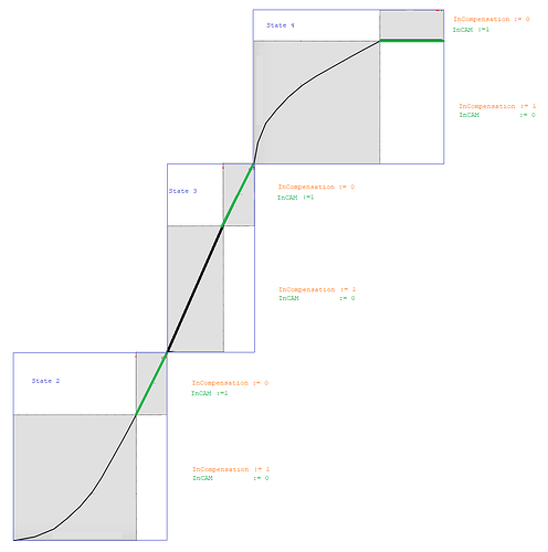
State 2 has its master lenght but now also an slave lenght which defines that the slave will move a certain distance while the master moves a certain distance.
The Event[0] and Event[1] are similar to the once bevor, again only leaving the state at the end of state.
State 3 , State 4 are again similar to State 2.
Due to the only usage of the Event with Transition “End of State” the CAM Automat will
stay in a defind Master/Slave Position given by the Size of the States.
Which States it will go through, is in this use-case, only dependent to “Signal1”
If you never SetSignal1 you end up never leaving State 1 and the slave will never move.
If you SetSignal1 in every state you will end up in state 3 were the slave runs synchron to the master.
If the SetSignal1 is sometimes triggered and sometimes not, you go through all states.
If you would use Transition “Immediatly” in combination with “Signal1” in an Event, the CAM Automat would immediatly with the signal change its State. In this case the lenght of a State can change, as it can happen that it will not be completed.
Sometimes we want the Automat to stay in its periodicy, sometimes we want it to react fast to an external signal. Thats why we have the option to set up different Events.
I hope i could help you understanding how the “Length” of a State is defined and how a State Transition by the Event can be understood.
If you are interessted in a deeper understanding of the CAM Automat, i have here the Link to the Documentation of CAM Automat.
Greetings
Michael
Thanks Michael for the reply. I was able to understand from your explanation about the events and compensation distance that goes into the axis feature.
My question is how come the synchronous happens at 500mm and last till around 525mm as can be seen in the trace for InCam. The Incompensation trace is zero during the InCam as you can see from the trace.
Hello,
sorry for the delayed answer but i was a bit busy in the last days.
As shown in the last post, we know that the CAM Automat is switching between
a compensation State and a Cam State. This is why the Signals for
“InCompensation” and “InCam” are opposite.
The Resolution of the Trace is generated by TC#1 and this means we do not see the full resolution of the 400µs cycle on the ACOPOS. To visualise the exact moment the State Transition is made you have to trace the ParIDs via a ParID-Trace on the ACOPOS.
Thats why the Position seems to jitter in the Trace, but in reality it will be more precise on the acopos.
The Position depends on the size of the States and the Master/Slave relationship.
And the States define which Output is set on the Functionblock.
Greetings
Michael


