Need help replicating a trajectory created with a digital twin in the PLC

Hello,

I build an AI model that creates trajectories for a 3DOF Delta Robot. I trained the model based on a digital twin of this robot and know that the created trajectories should be possible.
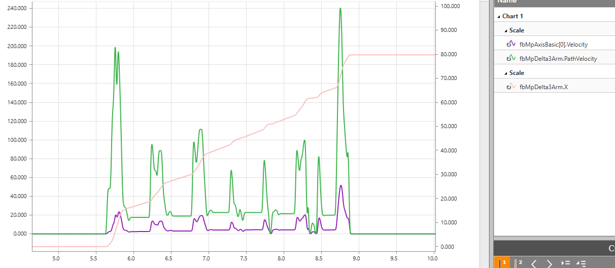
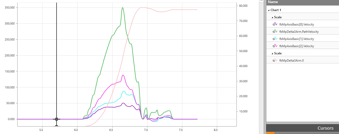
Now I want to replicate the trajectories on the real robot, but I can’t figure out how to get a smooth trajectory with correct velocities and accelerations.
Is there any way to do this?

Information about my setup:

  • I use mappMotion
  • I use the mapp Robotics 3-Axes Delta (A)
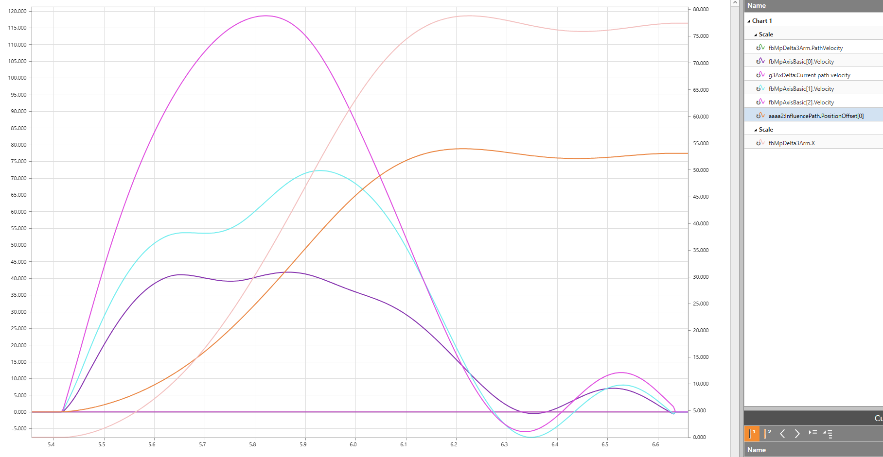
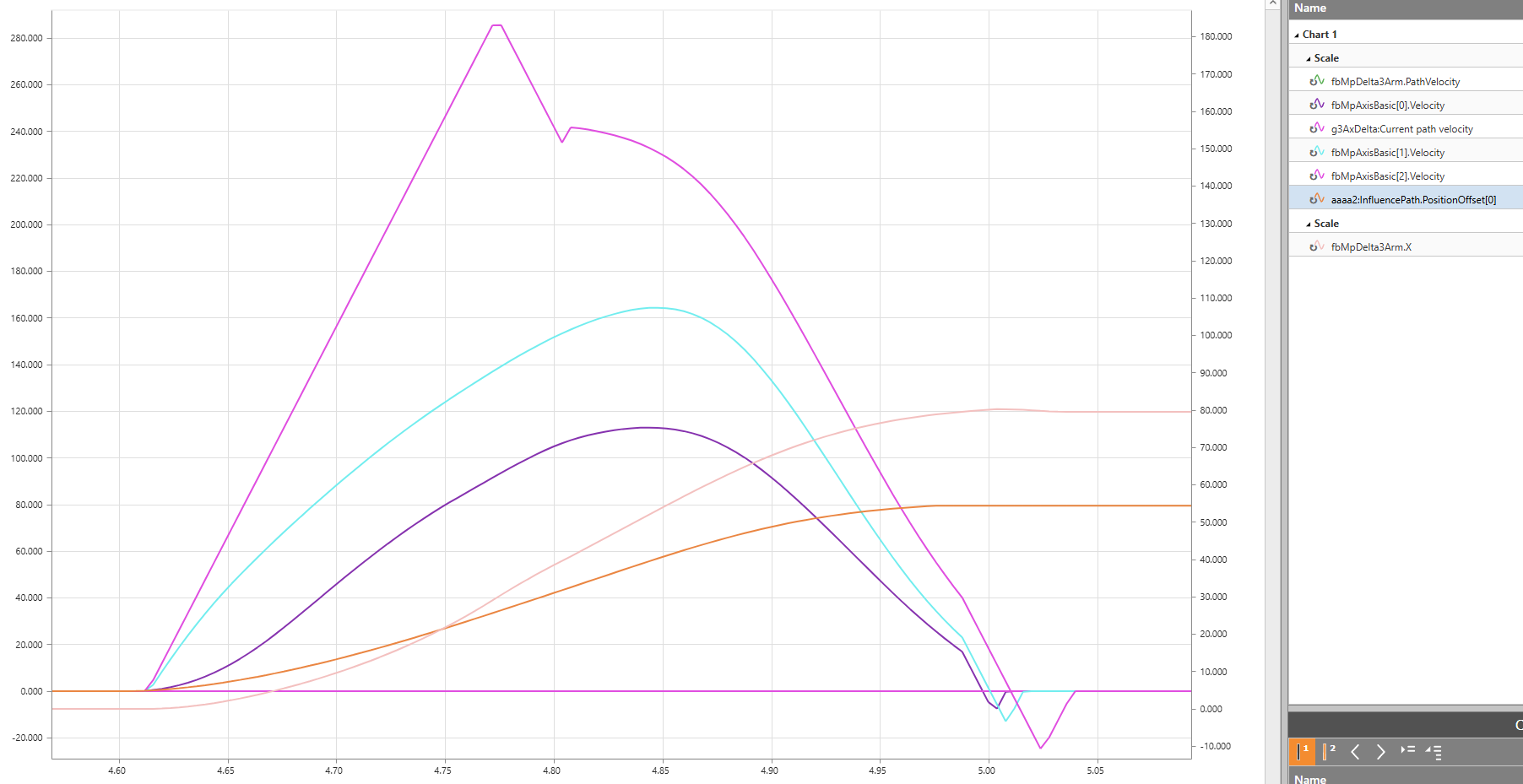
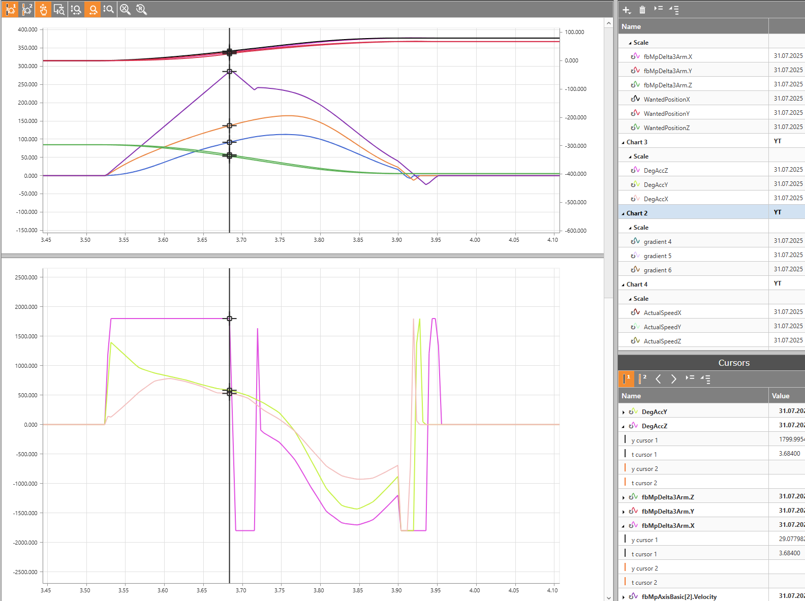
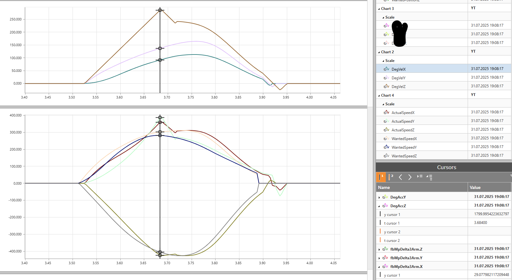
  • Information provided by my trajectory is: time, acceleration_x, acceleration_y, acceleration_z, velocity_x, velocity_y, velocity_z, coordinates_x, coordinates_y and coordinates_z.
  • The time between each trajectory point is 20 ms
  • My main CPU cycle is 4 ms
  • I use a synchronous motor

I tried ST-Motion Commands, but this only gets me the right position but not velocity or acceleration.
I also tried using GroupJog and setting max acceleration and desired velocity to get the correct position after the 20 ms, but my desired velocity and the actual velocity reached after 20 ms are different somehow.

Is there maybe a way to just set position and time and let the PLC handle the rest?

Hello,

I think you will need a CNC Program, as combining a Trajektory with Functionblocks is not as good ( Blending is limited )

I would point you to have a look into
G93 which sets the Feedrate in a mode like you descriped.
Position and Time should be possible.

The issue is now to make the G01 - Curves round, to not stop at each point.
You can try:

  1. standard roundings G126 or G127
  2. Use Compressor which generates a Spline from G01 sections

I know we had a similar requirement for the Dynamic Indentification Program used with the Functionblock below, maybe a look there can also help. Maybe there is a inspiration. But i used it last several years ago. So i don’t remember the details.

Looking forward to an interessting discussion.

Greetings
Michael

Hello,

I tried using G93 with G01 combined with the compressor.
I traced the path velocity and axis velocity this got me the following result.

I thought this may be because i hit some limit value i set, but the trace didn’t change when i set the path limits to some very high values:

  • Velocity = 2000 mm/s
  • Acc and Dec = 20000mm/s^2

The axis limits per axis are:

  • Velocity = 360 deg/s
  • Acc and Dec = 1800 deg/s^2

I also tried reducing the inverse feedrate to 1/6 of the original value, but that didn’t change the trace. The only thing different was that the velocity spikes were further apart.

When i use G00 without inverse feedrate the following gets traced:

After trying a few things. I created a trajectory where the max path acceleration will never be above 2000 mm/s^2 with the goal of 100% being below the limit.
The traced data is the following:

The velocity is way smoother but still spikes, even though it should in theory never get close to the limit values.

Next, i traced the same path but with G00 active. This gets a smoother trajectory:

What could be the reason that my trajectories are not getting smoothed especially for my first trajectory.
Only using G00 with compress is sadly not an option because i need the exact or almost exact vel and acc at specified times.

The following are my program code, my axisGroup setting and compressor settings.

N001 G90
N002 G101 X0.000001490 Y0.000001490 Z-296.479340643 F100*60
N003 G110 ACC=20000

N006 G04 2
N007 G93 

N008 G830
(N009 G126 100)

        N010 G01 X0.000001490 Y0.000001490 Z-296.479340643 F3000

        N020 G01 X0.692495704 Y0.305534899 Z-297.081734985 F3000

        N030 G01 X2.614991367 Y1.341828704 Z-298.874150962 F3000

        N040 G01 X5.534866452 Y3.341802955 Z-301.877234131 F3000

        N050 G01 X9.267935157 Y6.367304921 Z-306.081816554 F3000

        N060 G01 X13.664641976 Y10.294602811 Z-311.385963112 F3000

        N070 G01 X18.633627892 Y14.964306355 Z-317.642211914 F3000

        N080 G01 X24.081045389 Y20.184458792 Z-324.673451483 F3000

        N090 G01 X29.906132817 Y25.733003020 Z-332.303144038 F3000

        N100 G01 X35.949522257 Y31.359532475 Z-340.393379331 F3000

        N110 G01 X42.091780901 Y36.865779757 Z-348.794743419 F3000

        N120 G01 X48.305758834 Y42.140269279 Z-357.313536108 F3000

        N130 G01 X54.499635100 Y47.091060877 Z-365.730069578 F3000

        N140 G01 X60.455137491 Y51.613891125 Z-373.735532165 F3000

        N150 G01 X65.867373347 Y55.604109168 Z-380.935281515 F3000

        N160 G01 X70.459449291 Y59.021422267 Z-386.978879571 F3000

        N170 G01 X74.089714885 Y61.893814802 Z-391.693696380 F3000

        N180 G01 X76.762670279 Y64.237782359 Z-395.081579685 F3000

        N190 G01 X78.595706820 Y66.045084596 Z-397.271648049 F3000

        N200 G01 X79.770961404 Y67.335003614 Z-398.486554623 F3000

(N690 G126 0)
N690 G831
N999 M30


Hello,

i currently have not so much time to go over the whole topic… but i will try to give some short ideas.

If you have enought calculation Power on the PLC you can Reduce the LimitCheckResolution to the Interpolation Time. 0.004s This will improve the Velocity Profile, because the PathGenerator does the calculations more offten. But this will reduce your MaximumStop-Trajectory and increase the Load on the PLC.

I am not sure if there are more helpfull tips if using the Trajectory Planer of MappMotion.


If you can manage to generate your positions in the 4 ms distance instead of a 20 ms distance you can directly feed the positions to the Robot via “MC_BR_OnlinePathInfluence_N”
You have to start first a CNC-Program with a Blocking M-Function, so the CNC-Programm is active but will not execute a movement.
In this situation you can move the Robot via the inputs of the functionblock.
It will try to follow the Points only considering Axis-Limits.

This is a complet different UseCase as with a Program, so i don’t know if it fits in the later Targeted UseCase of the Application.

So far for the moment.
Greetings
Michael

Hello,

Thank you for your response.

I tried setting the LimitCheckResolution time to the Interpolation time of 0.004s. This led to a lot of small velocity spikes covering the whole velocity trace. But I will play with it some more.

I will try your second suggestion as well.
I will use any option to put my trajectory on the robot. It doesn’t matter how I do it.
Refining it will be done later, as I’m nearing a deadline at the moment and seemingly have tried almost everything.

If I use “MC_BR_OnlinePathInfluence_N” how fast will the robot try to reach the given position? Do I need to set acceleration limits for every move to not make the robot get to the desired position too fast?

Hello,

He will try to reach the given Position in the next Cycle… so if you have short Distances it will move slow , as soon the Distances will be longer it will speedup. If you have a Jump on the Inputs he will Jump with the Axis-Limits. – There is no additional interpolation made. That is why you have to pass a valid position in every cycle.

Its comparable to the CyclicPosition-Funktion Block on an Single Axis.

The Limits given by the Functionblock are only Limits, not the actual used Dynamic. They are updated only with the Enable.

Greetings
Michael

Hello,

i tried your suggestion with the “MC_BR_OnlinePathInfluence_N” and it kind of worked.
I used cubic spline interpolation to get my positions every 4 ms. Then I calculated the offset and put it into the function.

My traced data now looks something like this:

For the path where the max acceleration was never over 2000 mm/s^2.

And for the one that didn’t work at all last time.

As you can see, there is still a spike in the z-axis velocity curve. Other than that, the velocity curves are almost resembling the ones I expected. The other difference I noticed is that the axis velocities are greater than the ones I expected. For example, in the last trace, the max velocity of the z-axis is around 240, and the spike is around 285. The expected max velocity of the axis was 143.
Could this offset be why my trajectories didn’t work before?

My next question is, what do the spikes mean?
Is this because I’m too close to the axis limits, or is the position offset from one step to the next maybe too big?

Can this be solved via AutomationStudio or do I need to adjust my AI model and limit the possible velocities and accelerations a bit more?

For my last question. I know that the “MC_BR_OnlinePathInfluence_N” only looks at the axis limits. Is it safe to put the trajectories I just traced on an actual robot, or will it get destroyed? I presume the path limits are there for a reason.

I presume the spikes at the end of the traces are because of the end velocity after my last offset position. This should normally be no problem, but the axis velocities are greater than I expected.

Hello,

The Path-Limits are normaly to ensure a save Process and not to save the mechanic. The mechanic is protected by the axis limits. Some mechanics have also mechanical constrains which are considered in the mechanical description. Delta4Ax 4Ax-Telescope for example.

If you have vacuum gripper you would like to have cartesian limits to ensure you do not surpass your Process forces. In this case the PathLimits are a good option to reduce the mechanical limits to the process.

If you would move a delta as fast as possible you would remove all path limits and move by axes limits. Sometimes this is called Torque-Limited operation.

You should first clarify the issue with the limitation, to improve the velocity contour. But i do not think this would damage your kinematic if the axis limits are set well. The most relevant limit is the torque limit for the axis, because the gear is the most weekest part of the kinematic. The motor peak torque is typicaly higher and must be reduced.

The curve of the Velocity[2] seems running in an Acceleration limit. You can use the calculation function of MappCockpit-Trace Analysis to get the limiting value by differentation. Then you can check your configuration for this value.

I would also recoment to trace much more values like Q1,Q2,Q3 Positions and Velocitys to see if an Axis goes in an Limit. You can Trace inputs of OnlinePathInfluence.Position[0,1,2] to compare it to PCS Positions, to see how good the robot follows your values.
The limit of Variables is currently 32. Don’t spare here.

With the differentiation of the trace you can also check the speed of your Functionblock-Position input velocities.

If the Velocity is higher than expected you may have to check your Point Generator, because this is now mainly the driver for the cartesian movement.

If the cartesian speed is ok, and only axis speed is different the you would have to check parameters of Transformation/Mechanic.


I am happy to see how fast you implemented your point generator. :slight_smile: well done! Keep Going!

I hope my tips can help you go ahead.

Greetings
Michael

Hello,

Thank you for your help so far.
I traced what you sad and could see that the my z-axis was limited through max acceleration.
I also checked how well the robot follows my values and could see a maximum difference of 6 mm. This could maybe be because of the z-axis hitting a limit.

The Cartesian speed looked fine for the most part. I could see a spike, but I think that also was a result of my z-axis limit. The axis speed in deg/s is still way too high.

Where can i find these parameters for Transformation/Mechanic.
Are these the one from the ACOPOSmicro Servo Configuration under Mechanical elements? And what do i need to do with them. Could this be a gear ratio problem?

I have to add that for the trajectory where I limited the max acceleration the highest difference in wanted position and actual position was 2 mm. But this also was a way slower trajectory.

Hello,

The Single Axis Mechanical Definitions are not realy relevant in the simulation, as they only have influence of the real motor movement (which you can hardly diagnose in simulation). The Displayed positions are not influenced by this Settings.

The difference between cartesian and joint movement is given by the mechanical Transformation of the mechanic, which is set up by the mechanical Description in mappMotion. Here you have the length of the Arms of the manipulator and so on…

I am not sure how much expierience you have with the Parameters of Automation Studio
and if you have set up the Robot yourself or if you used a sample pre Configured Project.

You can have a look into this Thread were i explained most of the parameters which are relevant to set up a Robot. The Thread is little longer and goes up to chapter 4-AxesGroups.
Guide Commissioning

Greetings
Michael

Hello,

I finally got everything to work.

The problem was in the calculations for the digital twin I used to train my AI model with. It output angular velocities that were 0.8 times slower than they should have been.

This led to my trajectories being way too fast and hitting the axis limits when using time and place to replicate my trajectories.

On the other hand, while using the angular velocities, my trajectory was 0.8 times too slow to get to the position I wanted.

Now that it’s fixed. I have no problem with using “MC_BR_OnlinePathInfluence_N”, “G-Code” or “CycleVelocity” to replicate my trajectory.

Thank you for the help.

1 Like