I wanted to modify my custom mechanical system function for kinematics that would let me choose either elbow up/down. I wanted to do it by giving it another input, that would be global variable that would choose the solution. I am getting errors though that the variable is not defined and that it must be constant. The part about being constant is bit problematic in my case, because then I would not be able to choose the solutions. Later, I would like to modify the function even further, where there would be different calculation methods, where it would calculate all of them and I could choose which calculated solution I want.
Hello,
“First of all, some informations about used system MappMotion/Arnc0 and coding language would be helpfull so we could better adapt our answers. “
In Generall it is important to know that the Transformation is executed multiple times in the path-planer. (Preplanning, PathExecution)
So there are multiple calls at the same time to the function!
It is also important that the function-prototypes can not be change as far as i know, becuase the system has to be able to use them.
There are 2 ways of getting data to the Transformation, which i can see and have used.
- Mechanical Data
- Tool Data
Mechanical Data
This Data is intended to descripe the mechanical lenght and size and is considerd to be constant during runtime.
In mappMotion this data is passed via a Pointer to the Transformation functions. So all Functioncalls point to the same central storange.
The Pointer Access allows read and write access.
Data is shared for pre-planning and execution of path!
Tool Data
This Data is intended to descripe the tool of a kinematic and has a defined datatype. This Data can be provided from the Running Program.
This Data is passed through the motion system and is spezific for a Transformation function call. The System takes care that the correct data for
the current call is passed to the function.
Data is different for pre-planning and execution of path!
Not every application needs all Datapoints which are in the tool type, so it is possible to alter their usage for coustom kinematics, to generate for example a mode.
Conclution
I am not aware of a standard mechanism to support Kinematic “Modes” in mappMotion Transformations.
—–
Example for MappMotion - Enable 9 Different Modes via altering usage of Tool Parameter “Virtual tool tip”
If the selction of 9 modes would be enought, you can use the Virtual Tool Tip which is normaly intended for a “Lathe” Application.
The Implementation of a Direct Transformation could then look like this. Where Mode 0 can be completly different to Mode 1. - Every time the Tool gets changed by the Programm, the System can handle the change of the Transformation.
FUNCTION customDirectST

	IF data.Parameter.MechDimensionsAddr = 0 THEN
		data.Info.Status.Code  := 1;
		customDirectST := mcPATHGEN_CUSMECH_ERROR;
	ELSE
		// Get Mechanical Data
		pMechData ACCESS data.Parameter.MechDimensionsAddr;

		// Select Mode By
		CASE data.Parameter.Tool.VirtualToolTip OF
			mcTOOL_VIRTUAL_TOOL_TIP_POS0:
				// TRF Mode 0

				data.Output.TcpPos[0] := data.Input.JointPos[0];
				data.Output.TcpPos[1] := data.Input.JointPos[1];
				data.Output.TcpPos[2] := data.Input.JointPos[2];
				data.Output.TcpPos[3] := data.Input.JointPos[3];
				data.Output.TcpPos[4] := data.Input.JointPos[4];

				customDirectST := mcPATHGEN_CUSMECH_SUCCESS;

			mcTOOL_VIRTUAL_TOOL_TIP_POS1:
				// TRF Mode 1

				data.Output.TcpPos[0] := data.Input.JointPos[0];
				data.Output.TcpPos[1] := data.Input.JointPos[1];
				data.Output.TcpPos[2] := data.Input.JointPos[2];
				data.Output.TcpPos[3] := data.Input.JointPos[3];
				data.Output.TcpPos[4] := data.Input.JointPos[4];

				customDirectST := mcPATHGEN_CUSMECH_SUCCESS;

			ELSE
				// Not Implemented
				customDirectST := mcPATHGEN_CUSMECH_ERROR;
		END_CASE
	END_IF

END_FUNCTION
If your mechanic still used the normal Tool-Parameters, you will need to modify the
Toolhandling to not override the ToolTip. This can be done by modify the CNC-Syntax via AIL, but this should be topic for a later discussion.
Greetings
Michael
Hello,
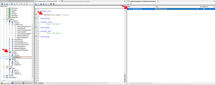
I forgot to mention the language and so on. The language is Structured text and MappMotion and such can be seen in the picture below.
I think I explained it a bit wrong. Because I have 3 axes redundant robot, there can be multiple solutions for one given point in 3D space. The robot is declared and will stay the same all the time, same for the tool, these do not change. I have 5 mathematical solutions for the kinematics, that should lead on different positions of joints. I wanted to know, if it can be done/should be done in 1 library, where these functions are.
Would it be better/possible to put all possible solutions and change it internally inside the function, i.e. there will be new input for chosen solution and inside the function would be IF statment, where “IF solution1 = true THEN…. IF solution2 = true THEN….” Or if I should make separate custom mechanical libraries, where each library would have its own solution and I would be switching between these libraries, but the robot would still be the same
Hello,
Thanks for providing the additional Information. Good that you use mappMotion and ST, so my example was already in the right direction, matching both.
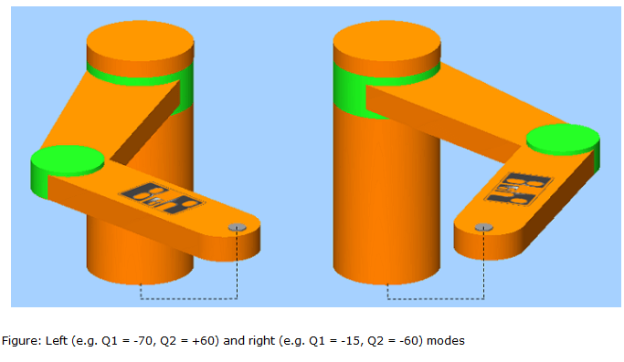
I think we talked about the same thing , because Right_Handed or Left_Handed (Mode) is pretty much the same than Solution1, Solution2, Solution3 of a redundant System.
Same TCP-Position → Different Joint-Positions.
You can only change from one Mode to another if in this Position both Modes result in the same Positions. For the SCARA Q1=0 Q2=0 Long-Arm can be both right and left.
But typicaly you would use a Joint Interpolation G100 to move from one Mode to another, as TCP positions can be skiped in this Interpolation.
The implementation mainly depends allways on the timing when somethings should be changed. And if it is possible to implement in that way.
Using different Functions
You can only change between these Library implementations with an reconfiguration of the axes Groupd by MC_BR_Process_Config/Param.
So very restrictive and high effort. → only use if the Robot (and calculation) would be drasticaly different.
Using same Functions
You have to decide how to generate the correct outputs, in the library function.
a) Automatic Selection
If the solutions are selected automaticaly, you have to take care to not have Jumps on the Position Outputs, the change of the selction can only take place in situations were are intersections between solutions.
(Instead of the ToolTip change in the First example you would have a computation logic to decide which Calculation is executed or which solution is used. )
b) Manual Selection
If an manual input from the Program leads to an change in the selected solution you need to have a possible Data provider, for your selction If or Case Statement.
(See First Posting - example)
Flexible, thinks can be changed during runtime via If/case Statements in Code → only use if calculations are similar and belong to somehow same mechanic.
As your calculations are all for the same Robot, i would definitly use the same Library Function with a propper implementation of the selection.
You told that you have always the same parameters for the tool, so you can use a part of Mechanical Data to descripe your tool-Geometrie, in this way, the tool-word would be completly free for usage of mode change. Would be a restriction for future use, but for the start a valid limitation.
If you have 5 Modes its lower than the possible 9 available.
So you can choose between Variant a) and b) in your Transformation Functions.
You can even use mcTOOL_VIRTUAL_TOOL_TIP_POS0 for Automatic , and mcTOOL_VIRTUAL_TOOL_TIP_POS1..5 for Manual selection of the Calculation Mode.
Hello,
i read your question again, and may add some points about the variables, i think i got this question not in the first posts completly.
If you implement a Transformation Function here for example the Inverse, you must follow the prototype which is provided from B&R, so data is the only Input which should be used.
But you can add as much local Variables as you want.
For Global Data there is the Mechanik Description. You can set up a coustom Datatype in the Library.
Then you can create a Instance of the Variable in an Task
Add the Variable to the Mechanic Description of the Coustom TRF Setting
The usage in the Transformation will look like this.
The Mechanical Data is shared by all Transformation Functions and is globlay available.
For the calculations in the Transformation Functions you should only use local Variables, as each instance is called multiple times.
Greetings
Michael
Hello,
sorry for the late reply. Thank you for the information as well! The way by changing tools would be nice, I just wanted to ask to that as well. Can it be used on inverse as well or just directs?I would like if the Direct and Direct derivative function would stay the same, but only change the outcomes of Inverse and Inverse derivative, so if this solution will tool changing would be possible as well. And since I am using MpRoboticsFlex block, there is no input for tool, so I assume there is needed some other block for it and some additions in the Configuration view in the mappMotion file ?
Thank you again, Jan
Hello,
The Tool-Data is available for all Transformation-Functions Direct, Direct-Derivative, Inverse, Inverse-Derivative. In only used the Direct to make an example. It is important that the Roundtrip Direct->Inverse will result in same Data, if we use the Data to only select a different solution it is possible that you don’t have to use it in Direct-Trf.
The SET_TOOL_PAR command does not require to configure the Tool-Feature in AxesGroup. So adding the addional Configuration Files is optional.
If you would like to set it from application i would recommand to use the Tool-Feature Configuration to set “keep current Data” , in this case you can then use the PLCopen Functionblock “MC_BR_SetToolPar”.
Greetings
Michael


