Hi,
At the moment I am commissioning the B&R system and ACOPOS P3 for axis control.
In my project I am using ACP10, and this library takes me the block MC_BR_SetHardwareInputs (end switch control). But it is don’t working.
All signals are correct, in my structure gGantryAxis I have correct edit signals of end switch, but in my structure gAxisX (for example, for standalone axes) I don’t see this signal. gAxis is a variable of ACP10AXIS_typ.
My ideas is absent. Can we help me?
Regarding,
Anton Paramonov
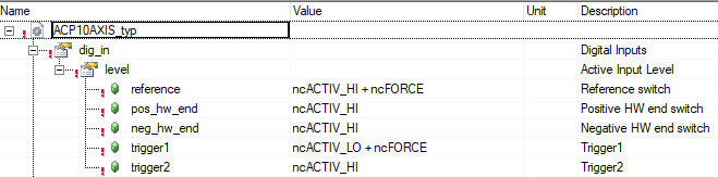
You have to add the ncFORCE option to the Init parameter Table of the Acopos:
In this case the reference and trigger 1 switch can be defined by the MC_BR_SetHardwareInputs.
Hi,
I am done it. But it is still not working
Maybe do you have any ideas?
Now I have an error “Both limit switches is closed”. I am inverse digital inputs in code. Maybe it is help me.
When forcing (+ncFORCE) is activated for an input the active level (ncACTIVE_HI/ncACTIVE_LO) is ignored.
The function block MC_BR_SetHardwareInputs sets the logical state of the input, e.g. “.PosHWSwitch” = TRUE … switch activated/closed.
Yes, I understood it, but how can I do it? My end switches still not working.
I understand which function to provide block MC_BR_SetHardwareInputs, but my axes don’t stop in test mode. I chose the “Parallel mode” for use code data of end switch for stop my axis.
I understand that it is not simple problem. And therefor I need to explain this problem more details.
As we know, it is a modernization the current project. Initially, I open the project in version AS4.12. Original project was made by AS4.6.3.55.
After it I had a problem with firmware for HW. Now, HW versions for all elements complies firmware in project.
Maybe it is the source of the problem?
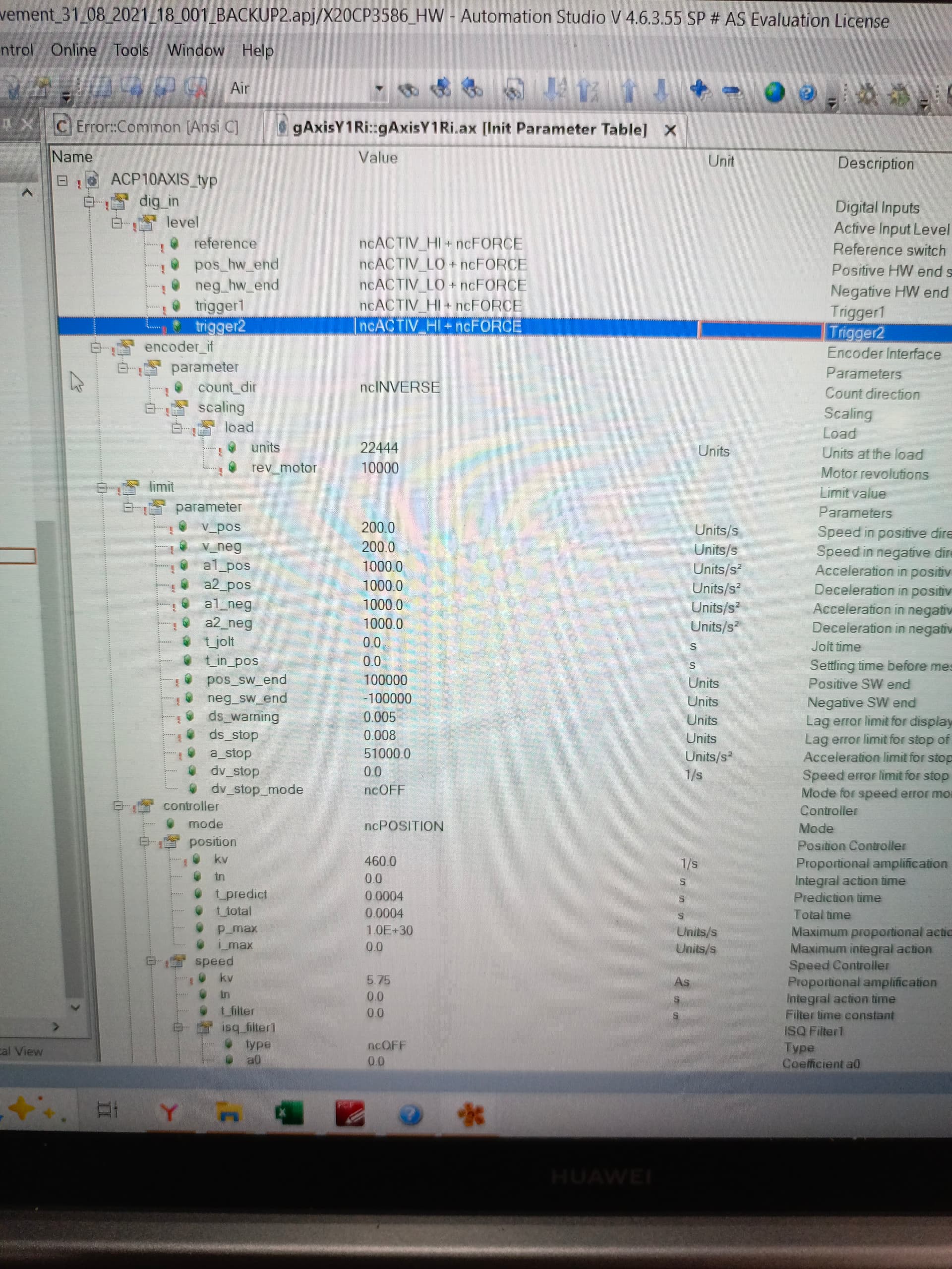
All functional blocks for ACP10 is available in project. Now, after change of level for HW end switches (in INIT parameters for axis) my Test is not starts of movement (SwitchON of controller is OK, Homing or Movements leads to a transition to “stopping mode”. Where can I see which problem I have?
And for this topic I am also share my screenshots with settings of axis.
Regards,
Anton Paramonov
Whats wrong, I dont understand.
P.S: if we need additional information, I can provide it
How you connect the limit switch and what the tipe of sensor are used
Hi,
Signals from limit switches are correct, LED indicators in input module show that signal is change. Therefore, it is connect right.
Limit switches have a normal closed contact.
Now, limit switches is working. But after triggering of limit switch drive switch to STOPPING mode. This mode can turn off after warm restart of PLC.
I understand that it is problem with my code. And now, I am searching the path of solve this problem
Ok just for clarification the physical limit switch in general used one time for every cycle of process and its homing. so its for defining the home position x0 Y0 z0 ..etc this in home cycles and it run just for the beginning AND then the limit switch calculated by the code like limit switch position positive +1000 and limit switch position negative -1000 .this how the limit switch used the physical used to determine the position 0.0.0 and then switch to the coded limit switch so this the system will work faster and easier to modify. Because if you use the physical limit switch there’s a time issue to be considered for every cycle need to check the status of this switch so it will consume time and effort but the programmed limit switch its just need to check the value calculated by the encoder also can check if the g.code or the command will trigger this switch before Run the program or command ( prevent any damage can happen)
This some information may that help also my English isn’t perfect so sorry for any grammar mistakes