The ModbusTCP Toolbox is a B&R software tool that allows you to connect to a X20BC0087 Modbus TCP bus controller and read/write Modbus registers and configuration data from it and any connected modules.
It is available for download on the B&R website: https://www.br-automation.com/en-us/downloads/control-and-io-systems/x20-system/bus-controller-modules/x20bc0087/modbustcp-toolbox/
This guide demonstrates how to set up the ModbusTCP Toolbox, get connected to the X20BC0087, and update its configuration using the Toolbox.
Connection Procedure
The below procedure will get you connected to the X20BC0087 using ModbusTCP Toolbox. You will first have to connect your laptop to the bus controller, then setup the ModbusTCP Toolbox and get connected to the bus controller.
X20BC0087 to Laptop Connection
Before getting started with the ModbusTCP Toolbox, you will need to get connected to your X20BC0087 bus controller over Ethernet.
-
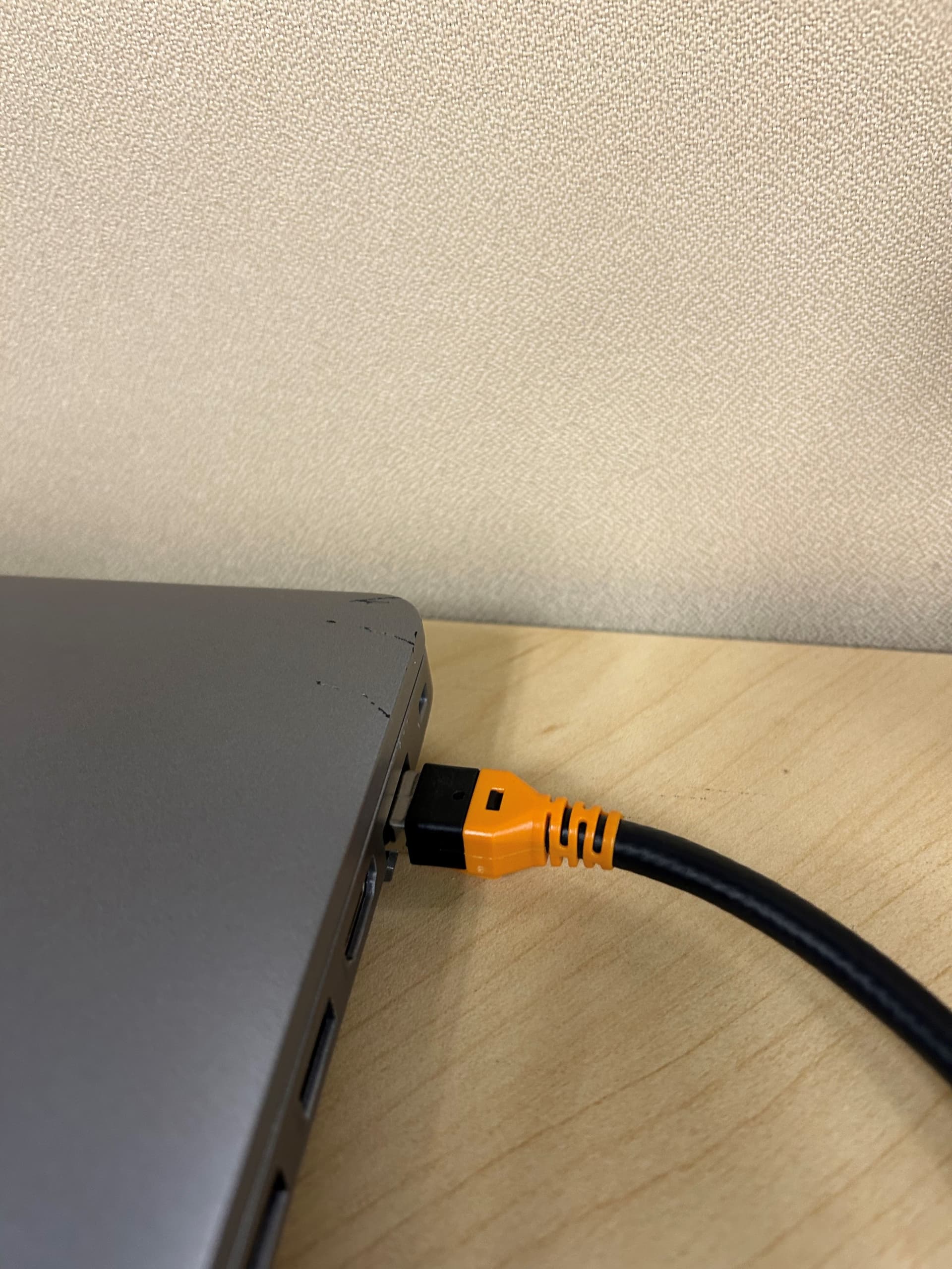
Connect either of the Ethernet ports on the bus controller to your laptop Ethernet port.
-
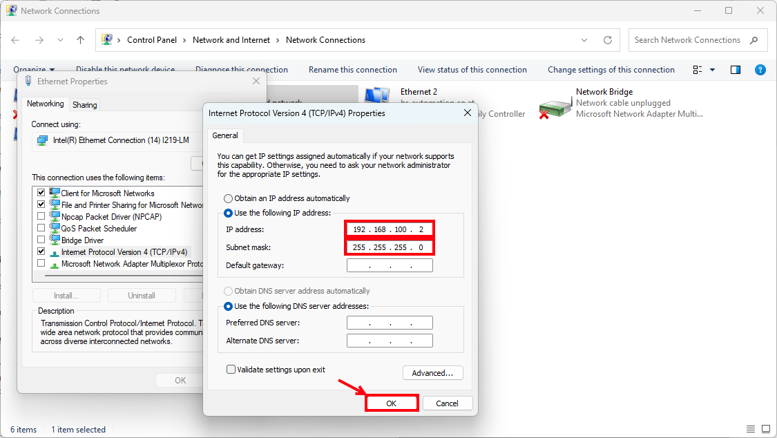
Set the IP address settings on your laptop to match the subnet of the bus controller
-
If you know your bus controller’s IP address and subnet, use that from here on out.
-
If you do NOT know your bus controller’s IP address, the best thing to do is set the factory default IP address (192.168.100.1) by setting the network address switches to 0xFF, procedure as follows (if this is not possible, contact support).
-
Using a flat-head screwdriver, set the network address switches on the bus controller to “F” and “F” as in the picture below.
-
Power cycle the bus controller. Once it comes back up, it should have the default IP address of 192.168.100.1 and port/interface number of 502, as in the Help page: B&R Online Help (8df24bd2-bbce-4d43-8d3b-dfd3f5076fd1), see below.
-
-
-
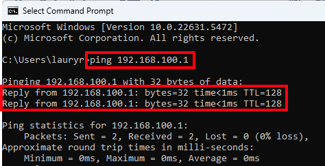
To test if you are connected, open Command Prompt and type the command: ping 192.168.100.1, and hit enter.
-
If you see replies coming back, you are successfully connected to the bus controller. Please proceed to the next section.
-
If you do NOT see replies coming back, either ICMP (ping protocol) is disabled on your laptop/network (if you are connected through a switch), or your IP address is set wrong on your bus controller. Please contact support.
-


ModbusTCP Toolbox Setup and Connection
To install the ModbusTCP Toolbox and get connected to your bus controller, follow these steps:
-
Download the ModbusTCP Toolbox from the link mentioned above (it is a Zip archive called “ModbusTCP_Toolbox_V1.5.0.zip”).
-
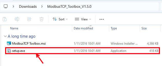
Extract the archive, navigate into the resulting folder, and then double-click the “setup.exe”. Follow the installation instructions.
-
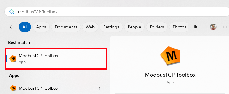
Once it is finished installing, open the ModbusTCP Toolbox by typing that in to the Windows search bar and opening the app.
-
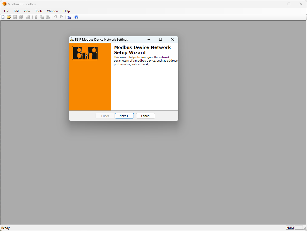
You should now see a blank window of the ModbusTCP Toolbox. We will now connect to your bus controller. To do so, navigate to “Tools > Configure Network Parameters”. This will bring up the Modbus Device Network Setup Wizard.
-
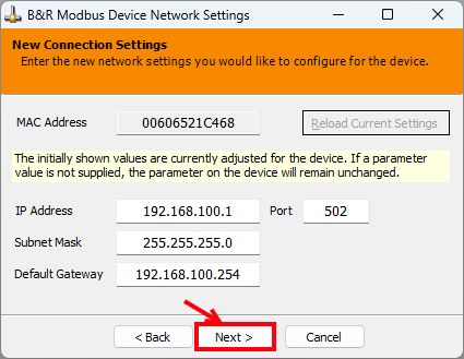
Set the correct IP address and port number (192.168.100.1, port 502, by default) and hit “Next”.
-
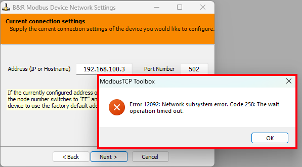
If it finds your bus controller, it will show you the below confirmation screen with MAC address and all network parameters. Here you can change the IP address and port configured on the bus controller if you would like to. Once any needed changes are made and all the settings look good, hit “Next”.
-
If it does not, you will get “Error 12092: Network subsystem error”; in this case, you will need to troubleshoot your network connection to the bus controller.
-
-
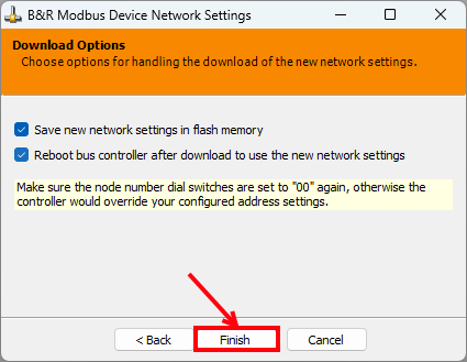
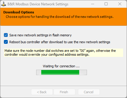
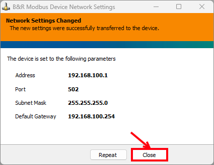
The final page will ask if you would like to set the settings to the bus controller flash memory, and whether you want to reboot. Once you have selected both (if desired), hit “Finish”. It will wait for a connection and then complete. If all looks good, you can now hit “Close”.
-
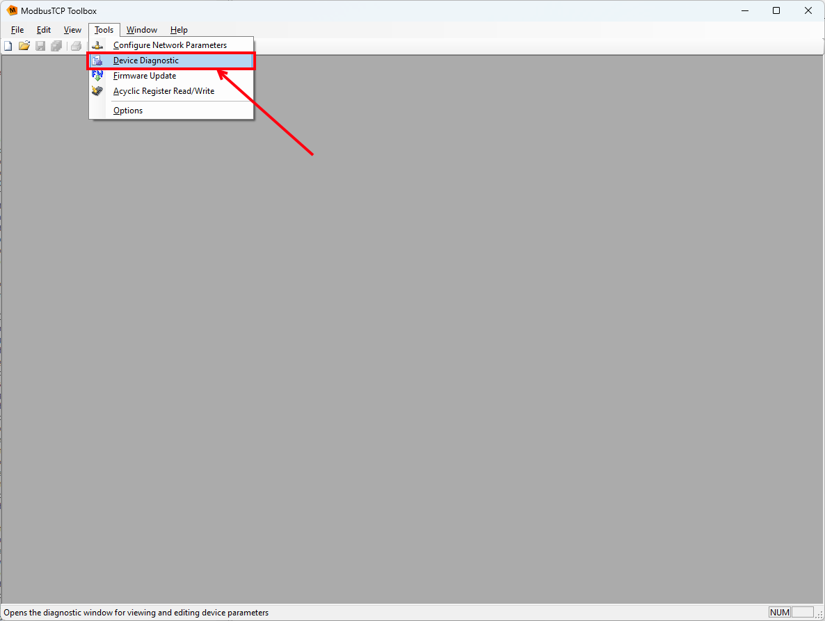
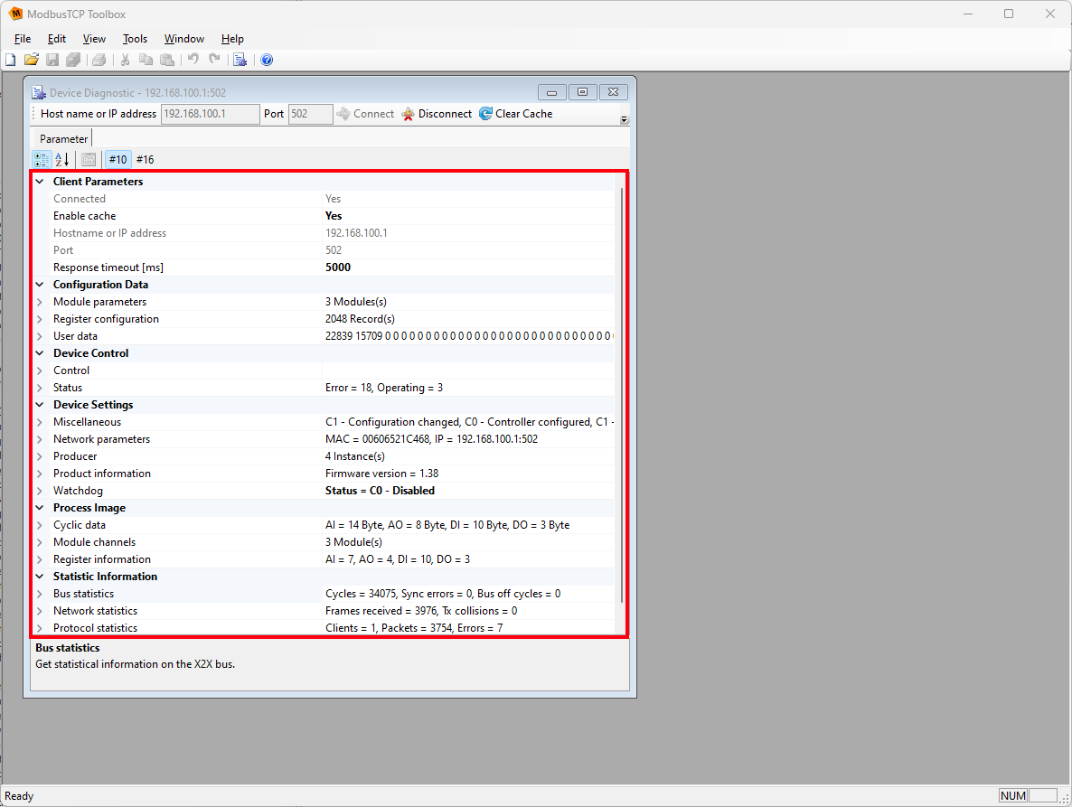
To connect to the bus controller and see the Modbus register layout and configuration, navigate to “Tools > Device Diagnostic”. This will open the “Device Diagnostic” window. At the top, enter the correct IP address and port (should be auto-filled) and hit “Connect”.
-
You are now connected to your bus controller! This page shows the various register spaces, including the bus controller and connected I/O module configuration data, as well as the “process image”, which contains all the live data. For more information about the process image, please see the following AS Online Help page: B&R Online Help (079fedd2-5ca8-4b6b-91a6-a5f23b61c059)


Updating the Configuration of the Bus Controller
In this example, a X20BC0087 connected to an X20AI2632 is configured in Automation Studio, the XML file generated, and the configuration loaded onto the bus controller using ModbusTCP Toolbox.
-
Create an Automation Studio project (if you don’t have one already) – ideally AS4.12 or AS6.3, the most current versions.
-
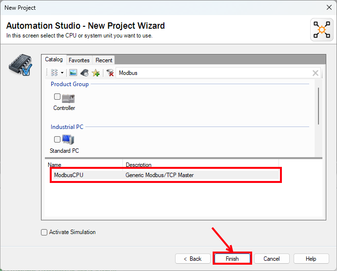
For the CPU, search for “Modbus” and select “ModbusCPU”.
-
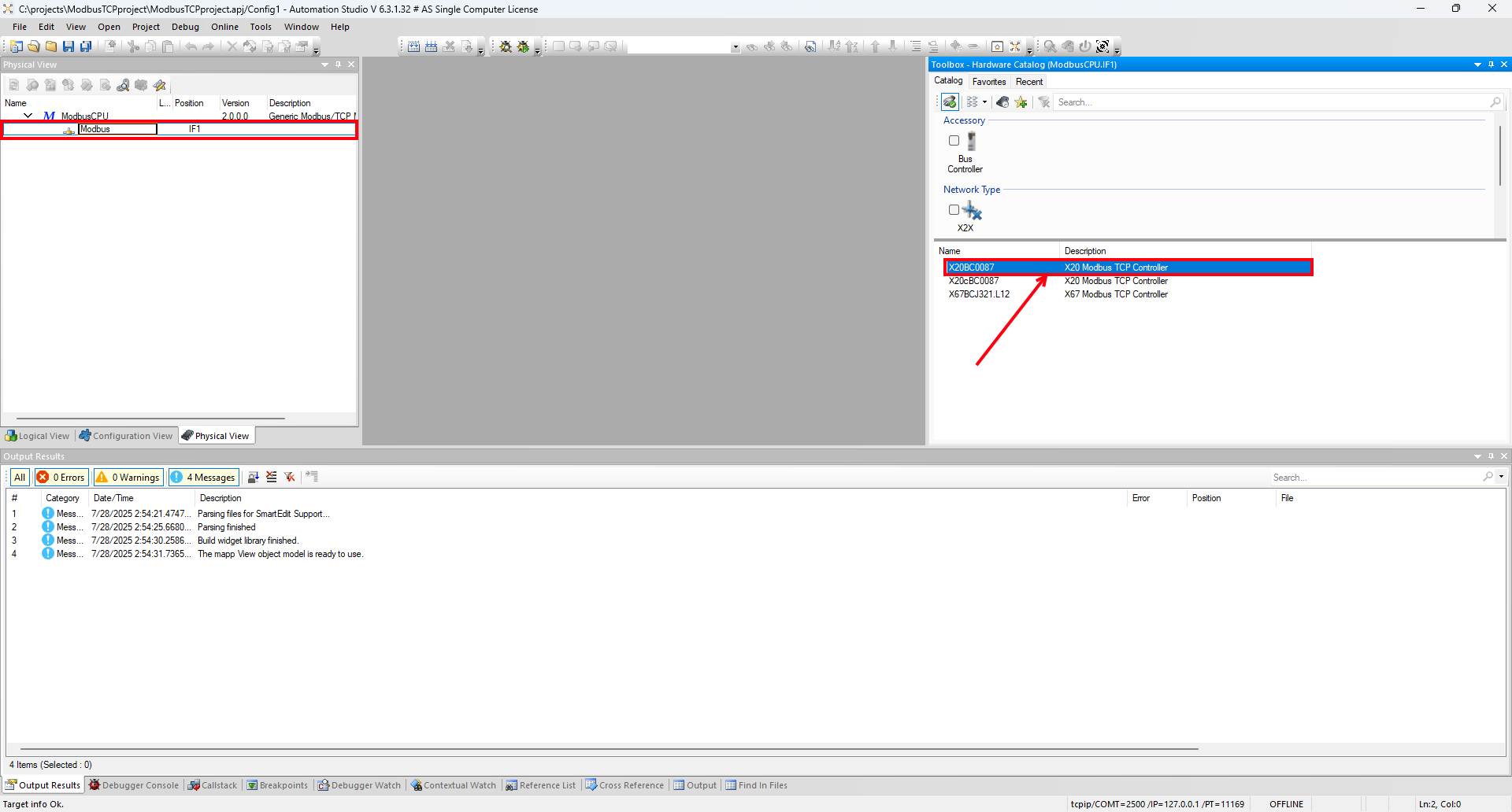
Add the bus controller to the Modbus interface by selecting “Modbus” in the Physical View and then double-clicking “X20BC0087” in the Toolbox.
-
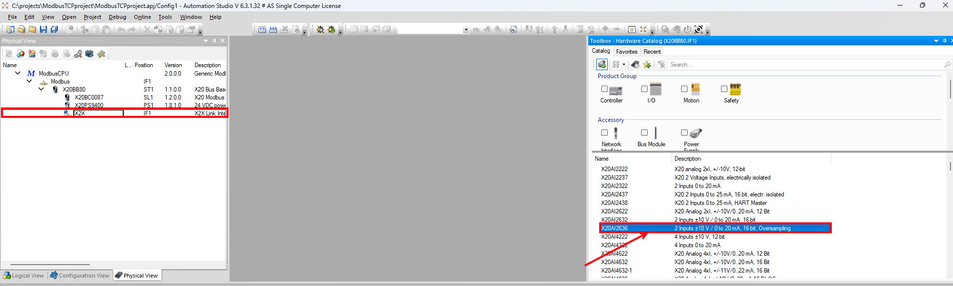
Add the required I/O modules (for the sake of example I have added an X20AI2632) to the X2X interface by selecting “X2X” in the Physical View and then double-clicking the modules in the same order as they are physically connected on your rack.
-
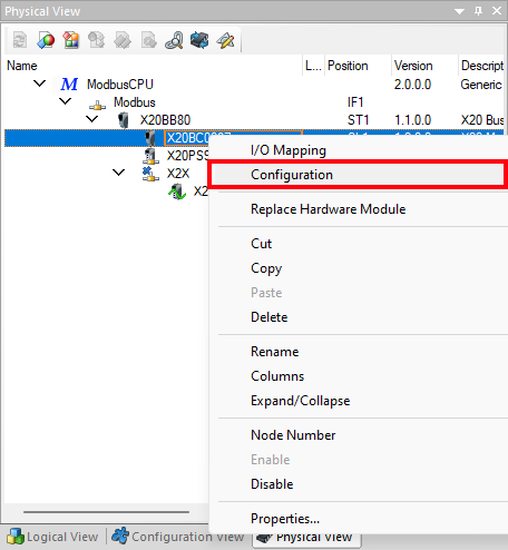
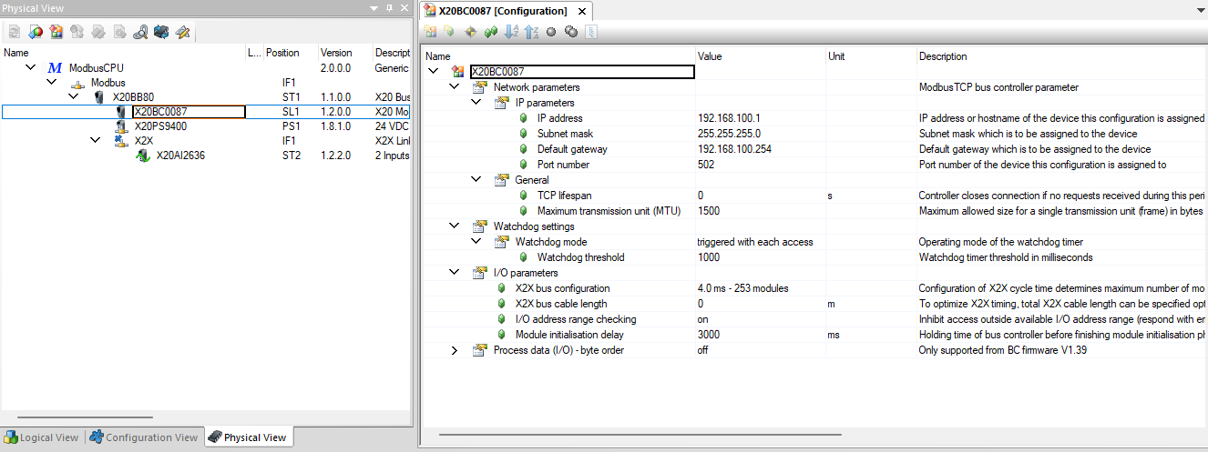
If needed, configure the Bus Controller by right-clicking it and selecting “Configuration”. You shouldn’t need to change anything other than IP address if it is not default.
-
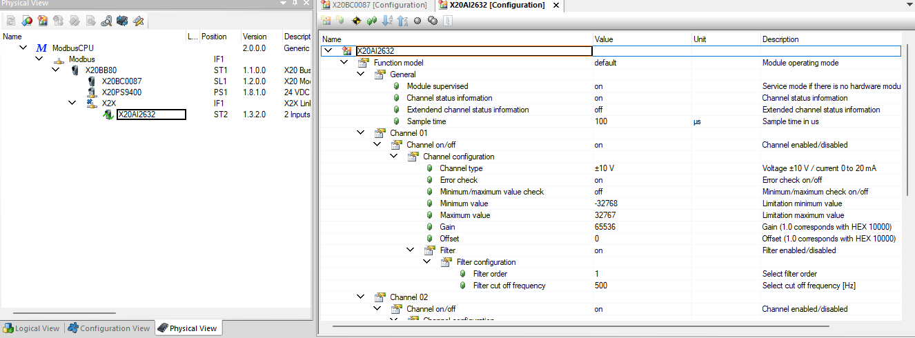
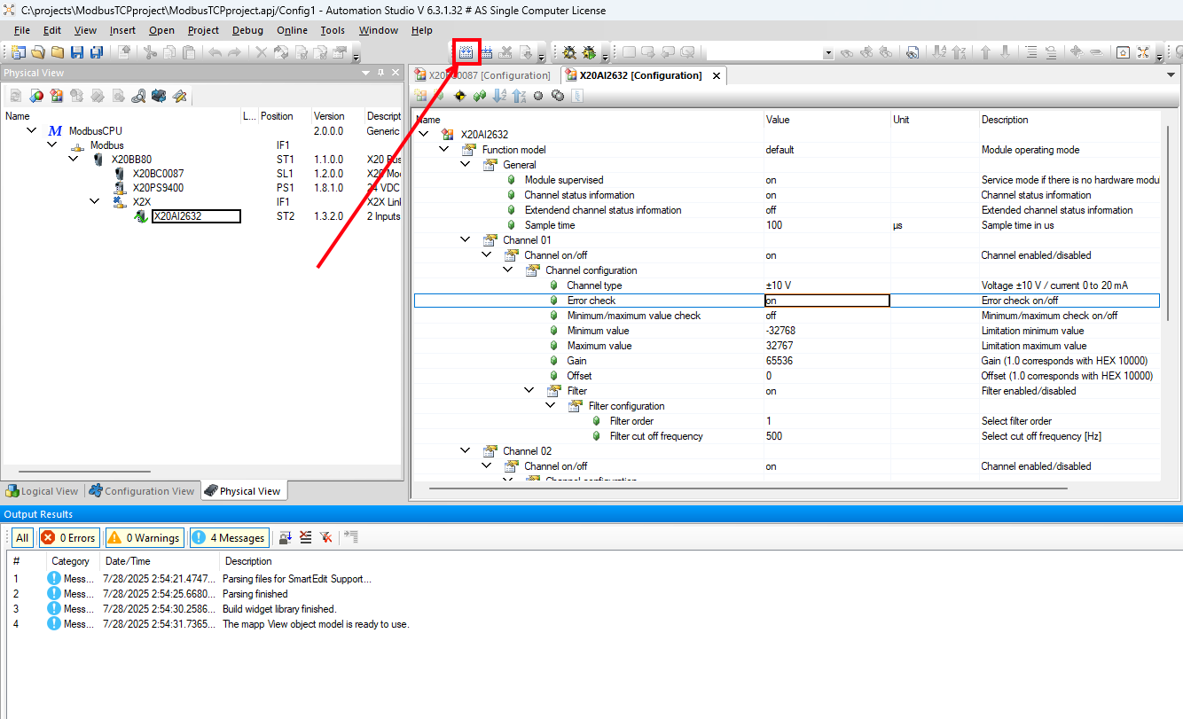
In a similar way, configure your I/O modules by right-clicking them and selecting “Configuration”. This will open up the configuration page, where you can set various values, such as the following. Double-click or hit the space bar while selecting the value to change it. See the below example for the X20AI2632 (similar to X204632):
-
Channel enabled/disabled

-
Filter configuration

-
-
Once you are done with your configuration, build the project by selecting the “Build” icon on the top toolbar.
-
After it has finished building, assuming there are no build errors, a pop-up will come up asking you to Transfer – select “Don’t Transfer”. Then find the line in the Output Results which shows the path starting with “Generating binary module C:\…\ModbusCPU” – remember that path.
-
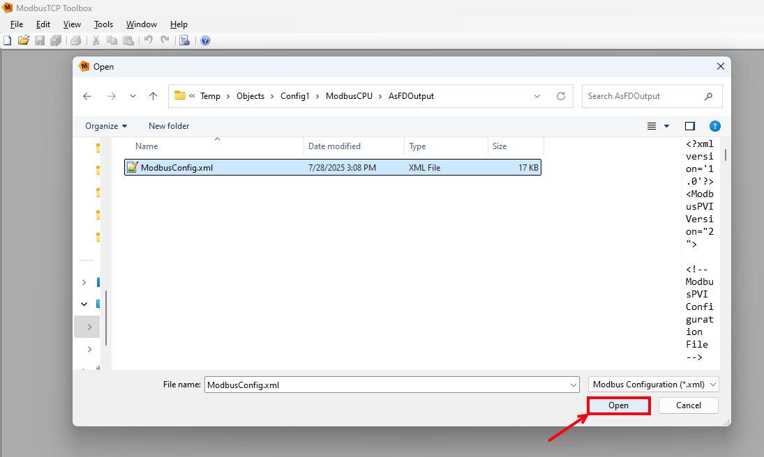
Now open the ModbusTCP Toolbox and connect to your bus controller by setting the network settings as in the previously advised procedure. Select “File > Open”, or the “Open” symbol in the top taskbar, navigate to the path to your ModbusCPU folder (C:\projects\ModbusTCPproject\Temp\Objects\Config1\ModbusCPU in my case). In that folder, open the “AsFDOutput” folder, select the “ModbusConfig.xml” file, and select “Open”.
-
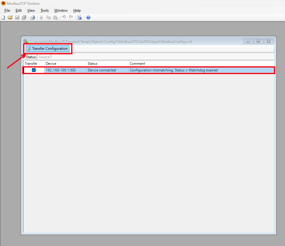
This will open a window showing the bus controller, and it should say “Configuration mismatching”. Select the bus controller and then hit “Transfer Configuration”
-
Once your bus controller comes back online, it will now have the updated configuration loaded onto it.


Additional Help and Resources
-
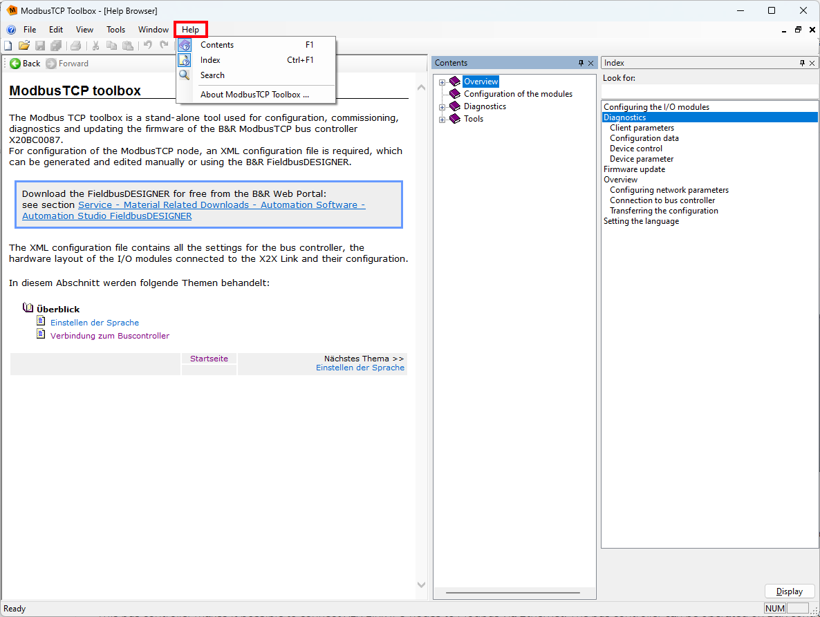
The ModbusTCP Toolbox built-in Help menu, accessible from the “Help” item on the top toolbox.
-
Additionally, Automation Help has a lot of good information about Modbus TCP connection to an X20BC0087. See the following links to the relevant Online Help pages.
-
General Modbus TCP section: B&R Online Help (e196c608-35cd-4ead-8fc1-e24d059dcb33)
-
Process image description: B&R Online Help (85683439-71ba-4ae0-857f-de928834ef57)
-
X20BC0087 section: B&R Online Help (c88326c0-d389-4051-b16d-49a41afa7154)
-
-
Finally, the X20BC0087 user’s manual has the most complete information about the bus controller, as well as some information about the ModbusTCP Toolbox. It can be downloaded here: https://www.br-automation.com/en-us/products/io-systems/x20-system/bus-controllers/x20bc0087/